Roll Forming vs. Press Brake Which Metal Forming Method Is Right for Your Production?

When considering roll forming vs press brake, you need a clear answer: the correct choice for your production depends on volume, part complexity, tolerance demands, material type, and total length—not on a universal winner.

Roll forming processes a continuous coil through successive roller stations; press brake forming bends individual sheet blanks one line at a time. This article provides a criteria-based framework and a breakeven way of thinking for your evaluation. Annual volume exceeding 50,000 units, combined with parts longer than 1.5 meters, signals the shift to roll forming—only when your product lifecycle surpasses two years. The distinct production process for each method determines your final decision.


Key Takeaways


  • Choose roll forming for high volumes over 10,000 parts per year and long parts over 1.5 meters.

  • Choose press braking for low volumes of 100 to 500 parts and complex shapes with multiple bends.

  • Roll forming has high tooling costs but low cost per part at scale.

  • Press braking has low tooling costs and fast setup for custom jobs.

  • Use the breakeven framework to compare your annual volume and part length before deciding.


Quick Answer: Roll Forming or Press Braking?


You need a fast decision snapshot before diving into the full comparison. The choice between roll forming vs press brake comes down to matching your production profile to the right process. Use the criteria below to self-classify your operation.


Choose Roll Forming When


Roll forming suits your operation under these conditions:

  • Your annual volume exceeds 10,000 parts with steady, predictable demand.

  • Your part features a continuous, uniform cross-section along its entire length.

  • Your profiles run long—typically beyond what a press brake can practically handle.

  • You need inline punching, notching, or cutting to eliminate downstream operations.

  • Your product design remains stable across a two-year or longer lifecycle.

High volumes justify the tooling investment because you amortize cost across thousands of units. The continuous nature of roll forming means your labor cost per part drops significantly at scale. You also gain tighter tolerance consistency across the entire production run.


Choose Press Braking When


Press braking fits your operation under these conditions:

  • Your batch sizes range from 100 to 500 units per job.

  • Your parts require multiple bend angles, radii, or complex geometries.

  • Your design changes frequently, requiring quick reprogramming.

  • You produce prototypes or custom fabrication runs.

  • Your part length stays within the practical limits of the machine throat.

Consider custom flashing fabrication as an example. A job shop produces 100 to 500 units per run with custom angles. Setup takes minutes, not hours. The press brake handles this work economically because tooling costs stay low—typically $300 to $1,000 compared to $5,000 to $30,000 for roll forming tooling.

Press brakes also excel when your parts need boxes, U-shapes, brackets, or enclosures. These non-linear shapes demand the flexibility that only a press brake provides. You reprogram the CNC controller and run the next job.


Roll forming and press braking each serve distinct production scenarios. Your batch size, part geometry, and design stability determine which process delivers better economics for your metal parts manufacturing operation. The table below summarizes the key decision factors.


Factor

Roll Forming

Press Braking

Annual Volume

Over 10,000 parts

100–500 parts per job

Part Geometry

Uniform cross-sections

Multiple bends, complex shapes

Setup Cost

$5,000–$30,000

$300–$1,000

Flexibility

Fixed profile tooling

Easy reprogramming

Ideal Parts

Rails, channels, frames

Cabinets, brackets, prototypes


This snapshot gives you a starting point. The sections ahead explain the mechanics, economics, and trade-offs behind each method so you can run your own numbers.


What Is Press Brake Forming?


press brake forming machine


How Press Brake Bending Works


Press brake forming operates as an intermittent, sheet-fed process. You start with a flat metal blank. The machine presses this blank between a punch and a V-die along a single straight line. You create one bend at a time. Then you reposition the part for the next bend. The process repeats until you complete all required bends.

This sequential nature distinguishes press braking from roll forming. You handle the part between each stroke. Springback occurs after every bend. You compensate by over-bending slightly. Modern CNC controllers store bend sequences with these compensations. You recall programs quickly for repeat jobs. Setup requires only standard tooling. You adjust the punch and die set for different angles and material thicknesses.

The intermittent cycle defines the economics of press braking. Each stroke takes seconds. But handling time between bends adds labor minutes per part. This trade-off matters as you scale production.


Strengths and Limits of Press Brake Forming


Press brake forming offers clear advantages for certain production scenarios. Tooling costs stay low. A typical setup runs $300 to $1,000. You gain high customization. You reprogram the CNC controller to change bend sequences. This suits custom fabrication and prototypes. A press brake handles thick materials effectively. You can bend plates up to several millimeters without issue. The ideal use case is low-to-medium volume production with shorter components.

But press braking has disadvantages you must consider. Cycle time is slower due to part handling. Labor cost per part rises with complexity. Manufacturing cost studies reveal the scale of this effect.


Batch Size

Labor Cost / Part (Manual)

Labor Cost / Part (Automated)

5

$4.96

$7.41

10

$3.50

$3.91

25

$2.63

$1.81

100

$2.19

$0.76


Manual bending costs $2.19 per part at 100 units. Automated bending drops to $0.76. For a 100-blank batch, the quality-adjusted cost per accepted part is $2.33 for manual and $0.77 for automated.

labor cost per part by batch size

Additional disadvantages include limited part length. A press brake has practical length limitations; beyond a certain point, handling becomes problematic. Complex bend sequences also challenge the operation. You cannot form multi-plane shapes in a single pass. You need separate positioning for each bend.

For metal parts manufacturing, this process remains essential for job shops. You produce custom brackets and cabinets with fast changeover. For flexible low-volume bending, a CNC press brake offers the fastest turnaround. The process excels where volume stays low and design variations run high. You gain maximum flexibility with minimal capital commitment.


What Is Roll Forming?

Roll Forming method

How Roll Forming Works


Roll forming is a continuous metal forming technique. You feed a flat metal coil into a series of matched roller stations. Each station bends the material by a small increment. The strip passes through progressive forming passes until it reaches the final cross-section. This gradual approach absorbs springback step by step. You avoid the sharp strain that a single press stroke creates.

The coil moves continuously through the line. You do not handle individual blanks between operations. Inline punching, notching, and cutting happen while the strip moves. The line produces finished profiles without stopping. This flow separates roll forming from any batch-based process.For high-volume production, roll forming is incredibly fast. Once the line is set up and running, it produces a continuous stream of finished profiles at linear speeds often reaching hundreds of feet per minute.


Strengths and Limits of Roll Forming


The advantages of roll forming center on speed and consistency. Most roll forming lines operate at 100 feet per minute, or roughly 30 meters per minute. Speed is adjustable based on production needs. Tube mill applications reach 1,000 feet per minute. Steel stud lines run at 500 feet per minute. You gain tight tolerances and consistent quality across the entire run. Part consistency holds because the tooling never changes mid-run. You can form long lengths and complex metal profiles in a single pass. These advantages make roll forming ideal for medium to large runs.

The disadvantages involve capital and flexibility. Initial tooling investment runs high. Design lead time is longer than press brake setup. You cannot easily change cross-sections for small runs. Re-tooling downtime hurts frequently changing designs. For metal parts manufacturing, roll forming rewards stable, high volumes. If your annual volume justifies the tooling, the amortized cost per part drops sharply. If not, the capital risk outweighs the speed benefit.


Roll Forming vs Press Brake: Comparison Matrix


A side-by-side comparison reveals the key differences between roll forming vs press brake across critical production factors. The matrix below covers volume, speed, complexity, length, tolerances, material thickness, cost per part, and lead time.


Factor

Roll Forming

Press Brake Forming

Production volume

Above 10,000 parts per year

100-500 units per batch

Production speed

Continuous, above 30 m/min

Stroke-limited, batch-based

Part complexity

Uniform cross-sections, single pass

Variable cross-sections

Part length

Unlimited practical length

Limited by handling constraints

Tolerances

Highly consistent at scale

CNC-dependent

Material thickness

Varies by machine

Adaptable to thicker material

Cost per part

Low at large scale production

Higher per part

Tooling lead time

Weeks to months

Minutes to hours


Volume, Speed, and Production Mode


Production volume defines the economic boundary between these methods. Roll forming operates as a continuous coil-fed process. The line runs steadily, forming profiles at speeds above 30 meters per minute. High volumes justify the initial tooling cost. This high volume production delivers low cost per unit when annual quantity justifies the investment.

Press braking works differently. You handle each blank through multiple strokes. Labor time per part stays higher due to handling between bends. For low batches, the lower tooling cost makes press braking the economical choice.

The production mode affects your workflow. Roll forming integrates inline punching, notching, and cutting. You eliminate secondary operations. The intermittent method usually requires upstream cutting. You add handling steps between processes.


Complexity, Length, Tolerances, and Material


Part geometry determines which method produces your design efficiently. The continuous process handles long, uniform profiles with complex cross-sections in a single pass. You achieve multiple bends and sharp corners without stopping. The profile remains consistent across every unit.

Press braking suits parts with variable cross-sections. You create boxes, enclosures, and brackets with different bend angles on each face. Length creates a limitation. Parts beyond a practical length become difficult to position accurately.

Tolerances and material thickness differ across methods. The continuous process delivers strict tolerances at scale. Fixed tooling ensures precision across thousands of units. A press brake adapts to thicker materials readily.

The complexity comparison reveals clear strengths for each method. Consider parts with multiple bends and varied radii.


Complexity Factor

Continuous Process

Intermittent Process

Non-right-angle bends

Handles efficiently in continuous process

Requires separate tools for each angle

Multiple bend radii

Single-tool setup for efficient production

Each radius requires a tool change

Production continuity

Continuous process avoids tool changes

Frequent tool changes cause delays

Sharp corners

Maintained through sequential forming steps

Air bending produces generous radii


The continuous process handles multiple non-right-angle bends efficiently. The single-tool setup enables multiple radii without interruption. Sharp corners remain crisp through the forming sequence. The intermittent process struggles with these factors. Each additional radius requires a tool change. Air bending produces generous radii that limit sharp corner capability.

The advantages of the continuous approach include consistency and quality at high volume production. The disadvantages of the intermittent approach include slower throughput per unit. For your metal parts manufacturing operation, this choice depends on your volume and complexity needs. In the manufacturing sector, custom metal profiles require matching method to requirements. The right decision reduces cost and lead time for your project.

The breakeven rule remains straightforward. Choose the continuous process for high-volume, long-length, dedicated profiles. Choose the intermittent process for low-to-medium runs with variable designs.


Cost, Tooling, and Lead Time


Tooling Investment and Setup Time


Roll forming requires dedicated roller sets machined for your specific cross-section. This tooling carries a high upfront cost and a long design lead time. You commit capital before you produce a single part. Press braking takes the opposite approach. You use standard punches and V-dies, so initial tooling cost stays minimal. Changeover happens fast through CNC programs. You load a program and run the next job within minutes.

The financial risk profile differs sharply. Roll forming ties your capital to one profile. Press brake forming keeps your options open for varied work. For a custom job shop, this flexibility matters more than raw speed. For a dedicated product line, the roller set becomes a fixed asset you amortize across production.


Cost Per Part and Material Utilization


Roll forming dilutes tooling cost at high volumes and lowers labor per unit. The line runs continuously, so you spread the fixed cost across thousands of meters. This makes roll forming cost-effective at high volumes. Press braking keeps per-part labor high, but it avoids capital risk at low volume. You pay for labor instead of tooling.

Material utilization favors roll forming. The process enables cut-to-length with minimal waste. You can integrate inline punching, notching, and embossing. Press braking usually needs upstream laser cutting and downstream deburring. Those secondary steps add handling and cost.

The payback math supports the investment case for high volumes. A machine costing $80,000 running at 15 meters per minute produces roughly 7,200 meters per eight-hour shift. At a selling price of $5 per meter, daily revenue reaches $36,000. After material and operating costs at 50% of revenue, monthly profit reaches $360,000 across 20 working days. Break-even arrives in 2–4 months.

Real-world payback periods vary by market. In developing countries, the payback period usually ranges from one to three years. A double layer roofing sheet line often achieves payback within 14–20 months. One project reached full payback in 19 months. Another case reduced the estimate from 24 months to 17 months. Managed efficiently, typical payback ranges from 12 to 24 months.

Weigh these advantages and disadvantages against your own volume forecast. The right choice depends on your batch size, budget, and finish requirements.


Real-World Example: Shelf Panel Production


The Scenario and the Trade-Offs


You manufacture shelf panels for storage systems. Each panel uses thin cold rolled steel sheet. Your annual volume is either low or high. This volume difference drives your process decision.

At low volumes, press brake forming offers a low-risk entry. Tooling costs stay under $1,000. You purchase pre-cut blanks from a laser cutting service. Each blank moves through multiple bend stations. Total cycle time per panel runs several minutes. Labor cost per unit remains high.

At high volumes, the economics change. Continuous roll forming amortizes the tooling investment across more units. You gain production speed and material efficiency. The scrap rate drops because the process cuts to length inline.


The Decision and the Outcome


For the high-volume scenario, you select a fully automated roll forming line. This roll forming line automates the complete work flow: unwinding, leveling with servo feeding and punching, cold rolling and forming, cutting and flanging, and robotic arm unloading. The line is configured with appropriate parameters for the panel dimensions and production requirements.


Metric

Efficiency Gain

Overall production efficiency

Up to 40% improvement

Production speed

50% faster than press braking

Labor costs

70% lower due to automation


The automated line reduces operator count significantly. The inline punching station eliminates a separate laser cutting operation. Material waste drops because the machine cuts each panel to exact length from the coil.

Compare this to the low-volume press brake job shop. That shop uses standard V-dies with a CNC backgauge. Each panel needs several separate bends. Total stroke and handling time per part is substantial. The finish quality depends on operator skill. Panel dimensions drift across the batch.

For your metal parts manufacturing operation, the volume determines the correct choice. Below 10,000 panels per year, the bending process wins on total cost. Above that threshold, the roll forming machine delivers better economics and consistent quality for your profiles.


How to Decide: A Breakeven Framework


Step 1—Calculate Annual Volume and Total Length


Start your evaluation by estimating annual volume and total linear length. Multiply your annual part count by the length of each part. This figure reveals your true production scale. For example, a shop producing a moderate number of short parts runs a modest total length, while a shop producing a high number of longer parts runs a high total length. The second operation crosses the threshold where roll forming tooling cost becomes diluted across enough units.

Identify your breakeven point. Below roughly 10,000 parts annually, press braking usually wins on total cost. Above that volume, roll forming labor savings dominate. The amortized tooling cost per part drops as volume rises. You pay once for the roller set and then run for years.


Step 2—Check Length, Cross-Section, and Secondary Operations


Examine your part length and cross-section next. Parts beyond a certain length (greater than typical press brake capabilities) make press braking impractical. The press brake throat depth and handling requirements limit you. Roll forming becomes the only reasonable option at those lengths. Your cross-section must also stay uniform along the entire part. Variable cross-sections favor the press brake.

Assess your secondary operations last. Continuous hole patterns, notches, or embossing add cost if you produce them separately. An inline punching roll forming line eliminates that separate punching operation. You form and punch in one continuous pass. This integration reduces handling, labor, and work-in-process inventory.

Your final choice depends on project needs, budget, and desired finish. Run your own numbers before you commit to tooling. A forming specialist can review your profiles and production needs against these criteria.


No universal winner exists in the roll forming vs press brake decision. The right method aligns with your batch size, cross-section design, part length, tolerance needs, and capital budget. Choose roll forming for high-volume, long-length, dedicated profiles with inline punching and cutting. Choose press braking for low-to-medium runs that demand agile customization and complex bend sequences. Before you commit to tooling, run your own numbers through the breakeven framework. Then consult a forming specialist or request a production assessment. A careful review of your part will confirm the right manufacturing path.


FAQ


What annual volume justifies roll forming tooling?


You need roughly 10,000 parts per year or more. Below that threshold, the amortized tooling cost per part stays too high. Above it, labor savings and continuous output dominate. Run your own breakeven linear footage before you commit capital.


Can a press brake form parts longer than practical limits?


No, not practically. Throat depth and handling limits make long parts difficult to position accurately. Parts beyond practical lengths push you toward roll forming. At those lengths, the continuous process becomes the only reasonable option.


Which method holds tighter tolerances at scale?


Roll forming delivers more consistent tolerances across a long production run. Fixed roller stations never change mid-run. A press brake depends on CNC accuracy and operator skill. Dimension drift can appear across a batch when handling varies.


Does roll forming eliminate secondary operations?


Yes, often. An inline punching roll forming line handles hole patterns, notches, and embossing in one continuous pass. You skip a separate punching station. Press braking usually needs upstream laser cutting and downstream deburring instead.


Which process suits prototypes and custom runs?


Press braking wins here. Standard punches and V-dies keep tooling cost low, and CNC programs change over in minutes. Roll forming requires dedicated roller sets with long design lead times. That commitment makes sense only for stable, high-volume profiles.
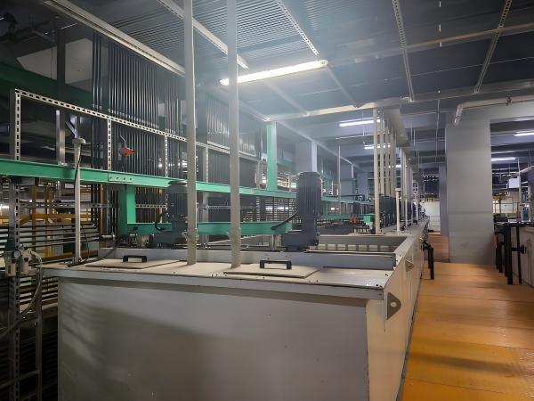
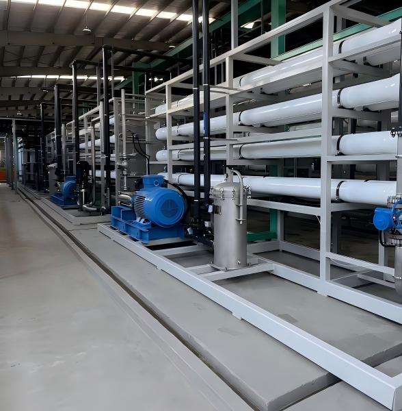
How Industrial Water Recycling Supports Sustainable Manufacturing

Manufacturing industries are facing increasing challenges in water management. Rising water demand, stricter environmental regulations, and the need for sustainable production are driving companies to rethink how they use and manage water resources.


Industrial water recycling provides an effective solution by treating wastewater generated during production processes and converting it into reusable water. Instead of discharging wastewater after a single use, manufacturers can recover valuable water resources and create a more sustainable production cycle.


Why Industrial Water Recycling Matters for Modern Manufacturing

Many industries, including new energy, semiconductor, electronics, electroplating, and chemical manufacturing, consume large amounts of water during production. At the same time, their wastewater may contain high levels of dissolved salts, heavy metals, or other complex contaminants.


A well-designed industrial wastewater treatment system can help companies:

  • Reduce freshwater consumption
  • Lower wastewater discharge volume
  • Improve environmental compliance
  • Recover reusable process water
  • Support long-term sustainable manufacturing goals


Advanced treatment technologies such as ultrafiltration (UF), reverse osmosis (RO), nanofiltration (NF), and zero liquid discharge (ZLD) are commonly integrated according to wastewater characteristics and reuse requirements.


Industrial Water Recycling Solution for New Energy Industry

As a wastewater treatment solution provider, Eragon Enviro Tech has developed water recycling systems for industries with challenging wastewater conditions.


For example, in a new energy industry wastewater reuse project, the wastewater contained high salinity and required stable treatment performance. The system adopted membrane-based treatment technologies, including pretreatment, UF and RO processes, to recover reusable water and support a zero liquid discharge (ZLD) target.


Through optimized process design, the treated water can be reused in production, reducing dependence on fresh water sources and improving overall resource efficiency.

Industrial wastewater reuse solution for sustainable manufacturing

(Internal link: Industrial Wastewater Reuse & ZLD Project)


Building a More Sustainable Water Future

Industrial water recycling is not only an environmental solution but also a strategy for improving operational efficiency.


For manufacturers, the right wastewater treatment technology can transform wastewater from a disposal challenge into a valuable resource. By combining water reuse systems, wastewater recycling technologies, and ZLD solutions, companies can move closer to a circular water management model.


With more than 20 years of industry experience, Eragon Enviro Tech provides customized wastewater treatment solutions for global customers, helping industries achieve reliable water reuse and sustainable development.

Industrial water recycling system for new energy wastewater treatment

(Internal link: Industrial Water Recycling Solutions)


FAQ

What is industrial water recycling?

Industrial water recycling is the process of treating wastewater generated from manufacturing processes and reusing the recovered water for production or other industrial applications.


Which industries need industrial water recycling systems?

Industries such as semiconductor manufacturing, battery production, electroplating, electronics, chemical processing, and metal finishing often require advanced water recycling solutions.


What technologies are used in industrial water recycling?

Common technologies include UF, RO, NF, MBR, evaporation, and ZLD systems. The selection depends on wastewater quality and water reuse requirements.

How Membrane Technology Is Transforming Industrial Water Reuse

Industrial water reuse is no longer just an environmental initiative—it has become a practical strategy for manufacturers facing rising water costs, stricter discharge regulations, and sustainability targets. Over the past two decades, membrane technology in wastewater treatment has fundamentally changed how industries manage and recycle water.


Today, technologies such as ultrafiltration (UF), nanofiltration (NF), and reverse osmosis (RO) enable facilities to recover high-quality water from complex industrial wastewater streams that were previously considered difficult to treat.


In practical engineering applications, selecting the best membrane system for wastewater recycling depends not only on water quality but also on long-term operational stability. Systems designed purely for high recovery without considering fouling risks often face performance decline within the first year of operation.


Why Membrane Technology Is Central to Water Reuse

Traditional wastewater treatment processes often rely on sedimentation, biological treatment, and chemical precipitation. While these processes remove many pollutants, they usually cannot produce water clean enough for reuse in industrial processes.


Membrane filtration works differently. It uses semi-permeable membranes to physically separate contaminants based on size and charge, allowing water molecules to pass while rejecting dissolved salts, heavy metals, and organic compounds.


Because of this capability, industrial membrane filtration systems are now widely used in sectors such as:

  • Electroplating and surface treatment
  • Semiconductor manufacturing
  • Chemical processing
  • Textile and dye production


These industries often generate wastewater with high salinity, heavy metals, or complex contaminants, making membrane-based treatment essential for reliable water recycling.


⇒Learn more about membrane technologies:

Industrial RO Membranes


From Wastewater to Reusable Process Water

One of the most significant advantages of membrane technology is its ability to transform wastewater into high-quality reusable water.


In a plating industrial park wastewater reuse project, wastewater contained fluctuating concentrations of heavy metals and dissolved salts from surface finishing processes. The treatment system combined chemical pretreatment with ultrafiltration and reverse osmosis membranes.


During initial operation, engineers observed rapid pressure increases in the RO units. Investigation showed that the root cause was unstable pretreatment rather than membrane failure. After optimizing solids removal and chemical dosing control upstream, the membrane system stabilized and achieved the target water recovery rate for industrial reuse.


This project highlighted a key engineering principle: membrane performance depends heavily on effective pretreatment design.


Today, the recovered water is reused within the facility for production processes, significantly reducing freshwater consumption and wastewater discharge.


Improving Water Recovery Rates

Compared with traditional treatment processes, membrane filtration offers a more predictable and controllable solution for industries seeking high recovery water reuse system design, especially in applications with strict reuse standards.


Reverse osmosis systems, for example, can remove over 95% of dissolved salts and contaminants, producing permeate suitable for many industrial applications.


In many reuse systems, membrane processes are combined with thermal technologies to achieve even higher recovery rates. For facilities aiming to approach zero liquid discharge (ZLD), membrane separation is often the first stage that concentrates contaminants before evaporation or crystallization.


This layered treatment approach allows plants to maximize water reuse while controlling operating costs.


Supporting Sustainable Manufacturing

Beyond technical performance, membrane-based water reuse systems support broader sustainability goals in industrial operations.


By recycling treated wastewater, manufacturers can:

  • Reduce freshwater intake
  • Lower wastewater discharge volumes
  • Improve compliance with environmental regulations
  • Stabilize long-term operating costs


For industries operating in water-scarce regions or under strict discharge limits, industrial water recycling systems based on membrane technology are increasingly becoming a strategic investment rather than an optional upgrade.


Engineering Perspective

From an engineering standpoint, membrane technology is most effective when integrated into a well-designed treatment train.


A typical industrial water reuse system may include:


Coagulation → Clarification → Filtration → Membrane Separation (UF/RO) → Reuse


When each stage is properly designed and controlled, membrane systems can operate reliably for years while delivering consistent water quality.


For companies planning new water reuse projects, the key is not simply choosing a membrane product but designing a system that considers pretreatment, scaling control, and long-term operation.


FAQ

Q: How does membrane technology improve industrial water reuse?

A: Membrane technology removes dissolved salts, heavy metals, and fine particles that conventional treatment cannot eliminate, allowing treated water to be reused in industrial processes.


Q: What is the best membrane system for wastewater recycling?

A: The best system depends on wastewater characteristics, but most industrial applications use a combination of ultrafiltration (UF) and reverse osmosis (RO) for optimal performance.


Q: Can membrane systems achieve zero liquid discharge?

A: Membrane systems are typically used as a pretreatment step in ZLD systems, concentrating wastewater before evaporation or crystallization.

How to Reduce Operating Costs in Industrial Water Treatment Systems

Operating costs are one of the most critical concerns in industrial water treatment projects. While initial system design often focuses on meeting discharge or reuse standards, long-term performance is ultimately defined by operating cost efficiency.


In practice, reducing industrial water treatment operating costs is not about cutting corners—it is about optimizing system design, improving stability, and selecting the right technologies based on actual wastewater characteristics.


Optimize Pretreatment to Avoid Downstream Costs

One of the most overlooked factors affecting wastewater treatment operating cost reduction is pretreatment design.


In a surface treatment industrial wastewater project, early operation showed frequent membrane fouling and unstable performance. Investigation revealed that incomplete removal of suspended solids and oil residues was causing excessive load on the downstream system.


After optimizing coagulation, flocculation, and solid–liquid separation, the system became significantly more stable. As a result:

  • Chemical consumption decreased
  • Membrane cleaning frequency was reduced
  • System downtime was minimized


This highlights a key engineering principle: a well-designed pretreatment stage can significantly reduce long-term operating costs.


Improve Water Recovery Efficiency

Improving water recovery rates in industrial wastewater treatment is another effective way to reduce costs.


Higher recovery means:

  • Lower freshwater consumption
  • Reduced wastewater discharge volume
  • Lower disposal costs


Technologies such as reverse osmosis (RO) are widely used to maximize water recovery. However, pushing recovery too high without proper design may lead to scaling and higher maintenance costs.


⇒Learn more about:

Industrial Reverse Osmosis Systems


From an engineering perspective, the goal is to find the optimal recovery balance, not simply the highest possible recovery.


Control Energy Consumption in Advanced Treatment

Energy consumption is a major contributor to industrial wastewater treatment operating expenses, especially in systems involving evaporation.


For high-salinity wastewater or ZLD systems, MVR (Mechanical Vapor Recompression) evaporation technology is often used because it is significantly more energy-efficient than traditional thermal evaporation.


⇒Related technology:

MVR Evaporation Systems


In one project, integrating membrane concentration before evaporation reduced the volume of wastewater entering the evaporator. This design change significantly lowered energy consumption and improved overall system efficiency.


This reflects a common optimization strategy: reduce load on high-energy processes by improving upstream efficiency.


Design for Stable Operation, Not Just Capacity

Many systems are designed based on peak capacity, but real operating conditions often fluctuate. Systems that perform well on paper may face instability in actual operation.


Unstable systems typically lead to:

  • Increased chemical dosing
  • Higher energy use
  • Frequent maintenance


In our project experience, systems designed with buffer capacity, proper equalization, and flexible control strategies consistently show lower operating costs over time.


Stability is one of the most important—and often underestimated—factors in cost control.


Select the Right Technology for the Application

There is no single "best" technology for all wastewater treatment systems. Choosing the wrong process can significantly increase operating costs.


For example:

  • Using advanced treatment where simple clarification is sufficient increases unnecessary cost
  • Relying only on membranes for high-salinity wastewater may lead to frequent scaling issues
  • Ignoring concentrate management can create hidden long-term costs


The key is to match the technology to the actual wastewater characteristics and treatment objectives.


Engineering Perspective

In practice, reducing industrial water treatment system costs is a result of multiple small optimizations rather than one major change.


Systems that achieve low operating costs typically share these characteristics:

  • Efficient and stable pretreatment
  • Balanced water recovery design
  • Optimized energy use in advanced processes
  • Integration between process stages
  • Long-term operational stability


Facilities that focus only on initial capital cost often face higher expenses later, while those that prioritize system design and operation tend to achieve better overall performance.


FAQ

Q: What is the biggest factor affecting wastewater treatment operating costs?

A: Pretreatment efficiency and system stability are often the biggest factors, as they directly impact chemical use, energy consumption, and maintenance frequency.


Q: How can energy costs be reduced in wastewater treatment systems?

A: Energy costs can be reduced by optimizing process design, improving upstream efficiency, and using energy-efficient technologies such as MVR evaporation.

RO vs Evaporation Which Technology Is Better for High-Salinity Wastewater?

High-salinity wastewater is one of the most difficult challenges in industrial water treatment. As industries push for higher water recovery and stricter discharge compliance, selecting the right technology becomes critical. The debate between RO vs evaporation for high-salinity wastewater treatment is common—but in practice, the answer is rarely one or the other.


Understanding the strengths and limitations of each approach is essential for designing an efficient and reliable system.


What RO Can and Cannot Do

Reverse osmosis (RO) is widely used in industrial wastewater treatment systems due to its ability to remove dissolved salts and produce high-quality permeate.


For moderate salinity wastewater, RO offers:

  • High water recovery
  • Lower energy consumption compared to thermal processes
  • Compact system footprint


⇒Learn more about:

Industrial Reverse Osmosis Systems


However, RO has limitations when dealing with high TDS wastewater. As salinity increases, osmotic pressure rises, reducing recovery rates and increasing the risk of scaling and fouling.


In practical terms, RO is effective up to a certain threshold. Beyond that, performance becomes unstable and operating costs increase.


When Evaporation Becomes Necessary

Evaporation technologies, particularly mechanical vapor recompression (MVR) systems, are designed to handle wastewater that membranes cannot treat efficiently.


For high-salinity or brine streams, evaporation provides:

  • Near-complete separation of water and dissolved solids
  • High recovery rates (approaching ZLD)
  • Ability to handle complex and variable wastewater


The trade-off is energy consumption. Evaporation is typically more energy-intensive than RO, which makes it less suitable as a standalone solution when salinity is still manageable by membranes.


Practical Insight: Why Hybrid Systems Work Best

In one industrial wastewater project involving surface treatment processes, wastewater contained heavy metals and high levels of dissolved salts. The initial design relied heavily on membrane treatment for water recovery.


While RO performed well at the beginning, increasing salinity in the system led to reduced recovery and frequent cleaning requirements.


After integrating an evaporation stage for concentrate treatment, the system achieved stable performance and higher overall recovery.


This reflects a common engineering conclusion:

RO and evaporation are not competing technologies—they are complementary.


Choosing the Right Approach

When evaluating RO vs evaporation for industrial wastewater treatment, the decision depends on several factors:


1. Salinity Level

  • Moderate salinity → RO is more efficient
  • High salinity → Evaporation becomes necessary


2. Water Recovery Targets

  • Standard reuse → RO may be sufficient
  • High recovery or ZLD → Evaporation is required


3. Operating Cost Considerations

  • RO → Lower energy, higher sensitivity to fouling
  • Evaporation → Higher energy, more stable at high salinity


4. Wastewater Complexity

  • Stable composition → RO performs well
  • Variable or complex streams → Hybrid systems are more reliable


Based on our previous projects, the most effective solution for high-salinity wastewater treatment is often a hybrid system:

Pretreatment → Filtration → RO → Evaporation


RO reduces the volume of water requiring evaporation, while evaporation handles the concentrate that membranes cannot process efficiently.


Systems designed with this balance tend to achieve:

  • Lower overall operating costs
  • Higher water recovery
  • More stable long-term performance


FAQ

Q: Is RO enough for high-salinity wastewater treatment?

A: RO is effective up to a certain salinity level, but for very high TDS wastewater, evaporation is usually required to achieve stable performance.


Q: Which is more cost-effective, RO or evaporation?

A: RO is generally more energy-efficient, but evaporation becomes more cost-effective when treating high-salinity or concentrate streams that RO cannot handle.

Typical Process Flow of Industrial Wastewater Treatment Plants

Industrial wastewater treatment plants are designed to handle complex and variable wastewater streams generated from manufacturing processes. While each project has its own characteristics, most systems follow a similar industrial wastewater treatment process flow, combining physical, chemical, and advanced treatment technologies.


Understanding this typical process flow helps engineers and plant operators design systems that are both efficient and reliable in long-term operation.


Step 1: Equalization and Flow Balancing

The first stage in most industrial wastewater treatment systems is equalization. Wastewater from different production lines is collected and stored in an equalization tank to balance flow rate and pollutant concentration.


In practice, this step is often underestimated. In one surface treatment wastewater project, fluctuations in influent quality caused unstable downstream performance during early operation. After optimizing equalization capacity and mixing, the overall system became significantly more stable.


A properly designed equalization stage ensures consistent feed conditions for the following treatment processes.


Step 2: Chemical Pretreatment

Chemical pretreatment is typically used to remove suspended solids, heavy metals, and emulsified contaminants. Common processes include:

  • pH adjustment
  • Coagulation and flocculation
  • Chemical precipitation


For industries such as electroplating or metal finishing, this stage is critical for removing copper, nickel, chromium, and other heavy metals.


From an engineering perspective, pretreatment is not just about meeting discharge standards—it is about protecting downstream systems, especially membrane filtration units.


Step 3: Solid–Liquid Separation

After pretreatment, the system moves into solid–liquid separation. Technologies such as sedimentation tanks, lamella clarifiers, or DAF systems are commonly used to remove flocs formed during coagulation.


The choice of technology depends on wastewater characteristics:

  • High-density solids → sedimentation or lamella clarifier
  • Oil and light particles → dissolved air flotation (DAF)


In projects with complex wastewater composition, combining multiple separation methods can improve overall efficiency.


Step 4: Filtration and Polishing

Following clarification, filtration processes are used to further remove residual suspended solids and improve water quality.


This stage may include:

  • Sand filtration
  • Activated carbon filtration
  • Multimedia filters


Stable filtration performance is essential before entering advanced treatment stages, particularly when membranes are involved.


Step 5: Membrane Treatment for Water Reuse

In modern industrial water reuse systems, membrane technologies such as ultrafiltration (UF) and reverse osmosis (RO) are widely applied.


These systems remove dissolved salts, fine particles, and trace contaminants, producing high-quality water suitable for reuse in production processes.


In one industrial park wastewater project, integrating RO systems after pretreatment allowed the facility to achieve a high water recovery rate. However, early membrane fouling issues highlighted the importance of stable upstream treatment. Once pretreatment conditions were optimized, the system achieved consistent performance.


⇒Learn more about:

Industrial Reverse Osmosis Systems


Step 6: Concentrate Management and Advanced Treatment

Membrane processes generate concentrated brine that must be managed properly. Depending on discharge requirements and project goals, different solutions can be applied:

  • Discharge after further treatment
  • Evaporation and crystallization
  • Zero liquid discharge (ZLD) systems


For high-salinity wastewater, MVR evaporation technology is often used to reduce liquid waste and recover additional water.


⇒Related technology:

MVR Evaporation Systems


Engineering Perspective

While the typical wastewater treatment plant process flow appears straightforward, real-world performance depends heavily on how well each stage is integrated.


In practice, most operational issues are not caused by a single technology failure but by imbalances between process stages—for example, inadequate pretreatment leading to membrane fouling, or insufficient equalization causing unstable system loading.


A well-designed system is not just a sequence of technologies—it is a coordinated process built around actual wastewater characteristics and long-term operational requirements.


FAQ

Q: What is the typical process flow of industrial wastewater treatment?

A: Most systems include equalization, pretreatment, solid–liquid separation, filtration, membrane treatment, and concentrate management.


Q: Why is pretreatment important in wastewater treatment plants?

A: Pretreatment removes solids and contaminants that could damage downstream equipment, especially membrane systems, ensuring stable operation.

Wastewater Treatment Challenges in Semiconductor Manufacturing

Semiconductor manufacturing relies heavily on water—especially ultrapure water (UPW)—for wafer cleaning, etching, and rinsing. As production scales up, so does the complexity of wastewater generated. Addressing semiconductor wastewater treatment challenges has become a critical priority for facilities aiming to maintain compliance, reduce costs, and enable water reuse.


Complex and Variable Wastewater Composition

One of the main challenges in wastewater treatment for semiconductor manufacturing is the highly variable composition of wastewater streams.


Different production steps generate wastewater containing:

  • Acids and alkalis
  • Fluoride compounds
  • Photoresist residues
  • Trace heavy metals such as copper and nickel
  • High total dissolved solids (TDS)


Because these streams differ significantly, a single treatment approach is rarely sufficient. In practice, effective systems rely on segregation of wastewater streams to allow targeted treatment.


Sensitivity of Advanced Treatment Systems

Semiconductor wastewater treatment often requires advanced technologies such as membrane filtration and reverse osmosis (RO) to achieve reuse-grade water quality.


However, these systems are highly sensitive to feedwater conditions.


In one industrial wastewater reuse project with characteristics similar to semiconductor applications, early operation showed rapid membrane fouling and unstable pressure. Investigation revealed that inconsistent pretreatment allowed fine particles and residual organics to enter the membrane system.


After optimizing coagulation, filtration, and process control, the system stabilized and achieved the expected industrial water reuse performance.


This reflects a key engineering insight:

membrane systems perform reliably only when upstream treatment is stable and well-controlled.


⇒Learn more about:

Industrial Reverse Osmosis Systems


High Salinity and Concentrate Management

Another major challenge is managing high-salinity wastewater streams generated after membrane treatment.


As facilities push for higher water recovery rates, the remaining concentrate becomes more difficult to handle. High TDS levels can lead to scaling, reduced membrane efficiency, and limited discharge options.


In many cases, additional treatment steps such as evaporation are required to manage concentrate effectively.


⇒Related technology:

MVR Evaporation Systems


Integrating membrane systems with evaporation technologies allows facilities to increase recovery rates while maintaining stable operation.


Balancing Water Reuse and System Stability

While many semiconductor plants aim for aggressive water reuse targets, pushing systems beyond their stable operating range can create new challenges.


High recovery designs without sufficient control may result in:

  • Increased fouling and scaling
  • Higher chemical consumption
  • Frequent system downtime


From an engineering perspective, the goal is not maximum recovery, but optimal recovery—where water reuse is balanced with long-term system reliability.


Operational Complexity and Process Control

Semiconductor wastewater treatment systems are often complex, involving multiple treatment stages and strict process control requirements.


Small variations in pH, chemical dosing, or flow distribution can significantly impact overall performance. This makes automation, monitoring, and operator training essential for maintaining consistent treatment results.


In real-world projects, systems with strong process control strategies tend to perform more reliably and maintain compliance over time.


Engineering Perspective

Addressing industrial wastewater treatment challenges in semiconductor manufacturing requires a holistic approach.


Successful systems typically include:

  • Segregation of different wastewater streams
  • Robust pretreatment to protect advanced processes
  • Integration of membrane and thermal technologies
  • Flexible design to handle variability
  • Focus on long-term operational stability


Facilities that consider these factors early in project planning are better positioned to achieve both compliance and sustainable water reuse.

Wastewater Treatment Solutions for Electroplating Industry

Electroplating is a critical process in modern manufacturing, but it also generates some of the most challenging industrial wastewater streams. Effective electroplating wastewater treatment solutions are essential not only for environmental compliance but also for improving water reuse and operational efficiency.


In this article, we explore how industrial facilities can address the complexity of electroplating wastewater through practical engineering approaches and proven treatment technologies.


Why Electroplating Wastewater Is Difficult to Treat

Electroplating wastewater typically contains a mixture of heavy metals, oils, surfactants, and suspended solids. Common contaminants include:

  • Copper, nickel, chromium, and zinc
  • Cyanide (in some processes)
  • Organic additives and surfactants
  • High total dissolved solids (TDS)


These pollutants vary depending on plating processes such as nickel plating, chromium plating, and precious metal finishing. This variability makes industrial wastewater treatment for electroplating plants particularly challenging.


In many cases, a single treatment method is not sufficient. Instead, a combination of physical, chemical, and advanced treatment technologies is required.


Typical Treatment Process for Electroplating Wastewater

A reliable electroplating wastewater treatment system usually includes multiple stages:


1. Chemical Pretreatment

pH adjustment, coagulation, and chemical precipitation are used to remove dissolved heavy metals by converting them into insoluble hydroxides.


2. Solid–Liquid Separation

Clarification processes such as lamella clarifiers or DAF systems remove the formed sludge and suspended solids.


3. Filtration and Polishing

Multimedia filters or activated carbon systems improve water quality before advanced treatment.


4. Membrane Treatment for Reuse

Advanced systems such as reverse osmosis (RO) are used to remove dissolved salts and produce reusable water.


⇒Learn more about:

Industrial Reverse Osmosis Systems


Achieving Water Reuse in Electroplating Plants

With increasing pressure on water resources, many facilities are moving toward industrial water reuse systems for electroplating wastewater.


In a surface treatment industrial park project, wastewater from multiple plating processes contained nickel, copper, chromium, as well as oils and suspended solids from pretreatment stages. The treatment system was designed to meet strict discharge standards while achieving a high water reuse rate.


During initial operation, fluctuations in influent quality caused instability in downstream processes. After optimizing pretreatment and solids removal, the system achieved stable operation, allowing treated water to be reused within the plant.


This project highlights an important insight:

stable pretreatment is the foundation of successful water reuse in electroplating wastewater treatment.


Managing High-Salinity Wastewater and Concentrate

Even after membrane treatment, electroplating wastewater systems often generate high-salinity concentrate streams.


When discharge is restricted or reuse targets are high, facilities may adopt zero liquid discharge (ZLD) solutions for electroplating wastewater. In such systems, evaporation technologies are used to further treat concentrated brine.


⇒Related technology:

MVR Evaporation Systems


By integrating membrane systems with evaporation, plants can significantly reduce liquid discharge and improve overall water recovery.


Engineering Perspective

From an engineering standpoint, the effectiveness of an electroplating wastewater treatment solution depends on how well the system handles variability.


In real-world projects, key success factors include:

  • Proper segregation of wastewater streams
  • Robust pretreatment for heavy metal removal
  • Stable solid–liquid separation
  • Integration of membrane and advanced treatment technologies


Systems that are designed only for average conditions often struggle under fluctuating loads, leading to higher operating costs and unstable performance.


FAQ

Q: What is the best treatment method for electroplating wastewater?

A: There is no single best method. Most systems combine chemical pretreatment, clarification, filtration, and membrane technologies to achieve stable performance.


Q: Can electroplating wastewater be reused?

A: Yes. With advanced treatment such as reverse osmosis, electroplating wastewater can be treated and reused for industrial processes.

Water Treatment Solutions for Chemical Manufacturing Plants

Chemical manufacturing plants generate some of the most complex wastewater in industrial production. With diverse raw materials, multiple process steps, and variable operating conditions, designing effective water treatment solutions for chemical manufacturing plants requires a practical, experience-based approach.


Beyond meeting discharge standards, many facilities are now focused on industrial water reuse systems, cost control, and long-term operational stability.


Why Chemical Wastewater Is Challenging

Unlike relatively consistent industrial streams, chemical plant wastewater treatment must deal with:

  • High COD and complex organic compounds
  • Variable pH conditions
  • Dissolved salts and high total dissolved solids (TDS)
  • Heavy metals and process-specific contaminants


In many projects, wastewater characteristics fluctuate significantly depending on production schedules. This variability is one of the main reasons why standard treatment designs often fail to perform consistently.


A Practical Treatment Approach

A reliable industrial wastewater treatment system for chemical plants typically includes multiple stages:


1. Equalization and Segregation

Balancing flow and separating high-strength streams helps stabilize downstream processes.


2. Chemical and Biological Pretreatment

Coagulation, flocculation, and in some cases biological treatment are used to remove organics and reduce pollutant load.


3. Solid–Liquid Separation

Clarification ensures that suspended solids are removed before advanced treatment.


4. Advanced Treatment for Reuse

Membrane technologies such as reverse osmosis (RO) are widely used to remove dissolved salts and produce reusable water.


Moving Toward Water Reuse

In recent projects, many chemical manufacturers have shifted from simple compliance to water reuse and recovery strategies.


In one industrial wastewater treatment project with characteristics similar to chemical manufacturing, wastewater contained mixed contaminants including dissolved salts, residual organics, and suspended solids. During early operation, unstable pretreatment led to frequent membrane fouling and reduced system efficiency.


After optimizing pretreatment and improving solids removal, the membrane system achieved stable performance and enabled consistent water reuse within the plant.


This experience highlights a key point:

water reuse in chemical wastewater treatment depends more on stability than on technology selection alone.


Handling High-Salinity Wastewater

As reuse rates increase, managing high-salinity wastewater becomes a critical challenge.


Reverse osmosis systems can recover a large portion of water, but they produce concentrated brine streams that require further treatment. In chemical plants with strict discharge limits, this concentrate cannot be discharged directly.


In such cases, integrating evaporation systems is often necessary.


By combining membrane systems with evaporation, facilities can significantly reduce wastewater volume and move toward zero liquid discharge (ZLD).


Balancing Cost and Performance

One of the most common questions in industrial water treatment for chemical plants is how to balance cost and performance.


In practice, overly complex systems may increase capital and operating costs without delivering proportional benefits. On the other hand, under-designed systems often lead to instability and higher long-term expenses.


From an engineering perspective, the most effective solutions are those that:

  • Match technology to actual wastewater characteristics
  • Optimize pretreatment to protect advanced systems
  • Balance water recovery with operational stability
  • Minimize energy consumption in high-load processes


In real-world applications, successful chemical wastewater treatment solutions are rarely defined by a single technology.


Instead, they are built on:

  • Careful analysis of wastewater composition
  • Flexible system design
  • Integration of multiple treatment stages
  • Focus on long-term operation rather than short-term targets


Facilities that approach water treatment as an operational system—rather than a standalone project—are more likely to achieve sustainable performance.


FAQ

Q: What is the best water treatment solution for chemical manufacturing plants?

A: There is no single solution. Most systems combine pretreatment, clarification, membrane filtration, and sometimes evaporation depending on wastewater characteristics.


Q: Can chemical plant wastewater be reused?

A: Yes. With proper treatment design, including RO and advanced processes, wastewater can be reused for various industrial applications.

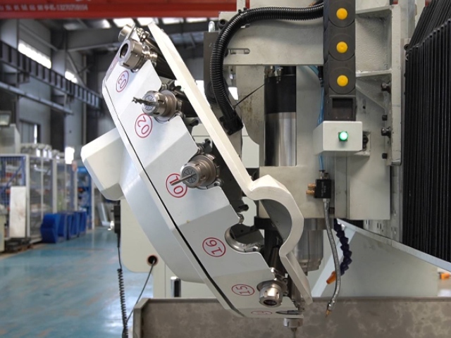
Can a CNC router cut metal?

Can a CNC Router Cut Metal? Yes, But Here’s What You Need to Know

If you’re in manufacturing, prototyping, or custom fabrication, you’ve likely asked: Can a CNC router really cut metal? The short answer is yes – but with important limits.

Unlike CNC mills or lasers, standard CNC routers are built for soft materials like wood, plastic, and foam. However, with the right setup, they can handle non-ferrous metals such as aluminum, brass, copper, and magnesium.

🔧 Key Requirements for Cutting Metal with a CNC Router:

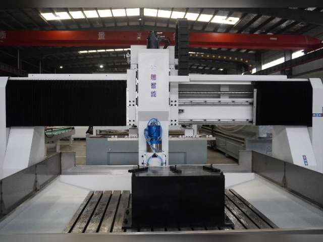
1.Rigidity – Metal cutting creates vibration. A sturdy frame (cast iron or heavy steel) is essential.

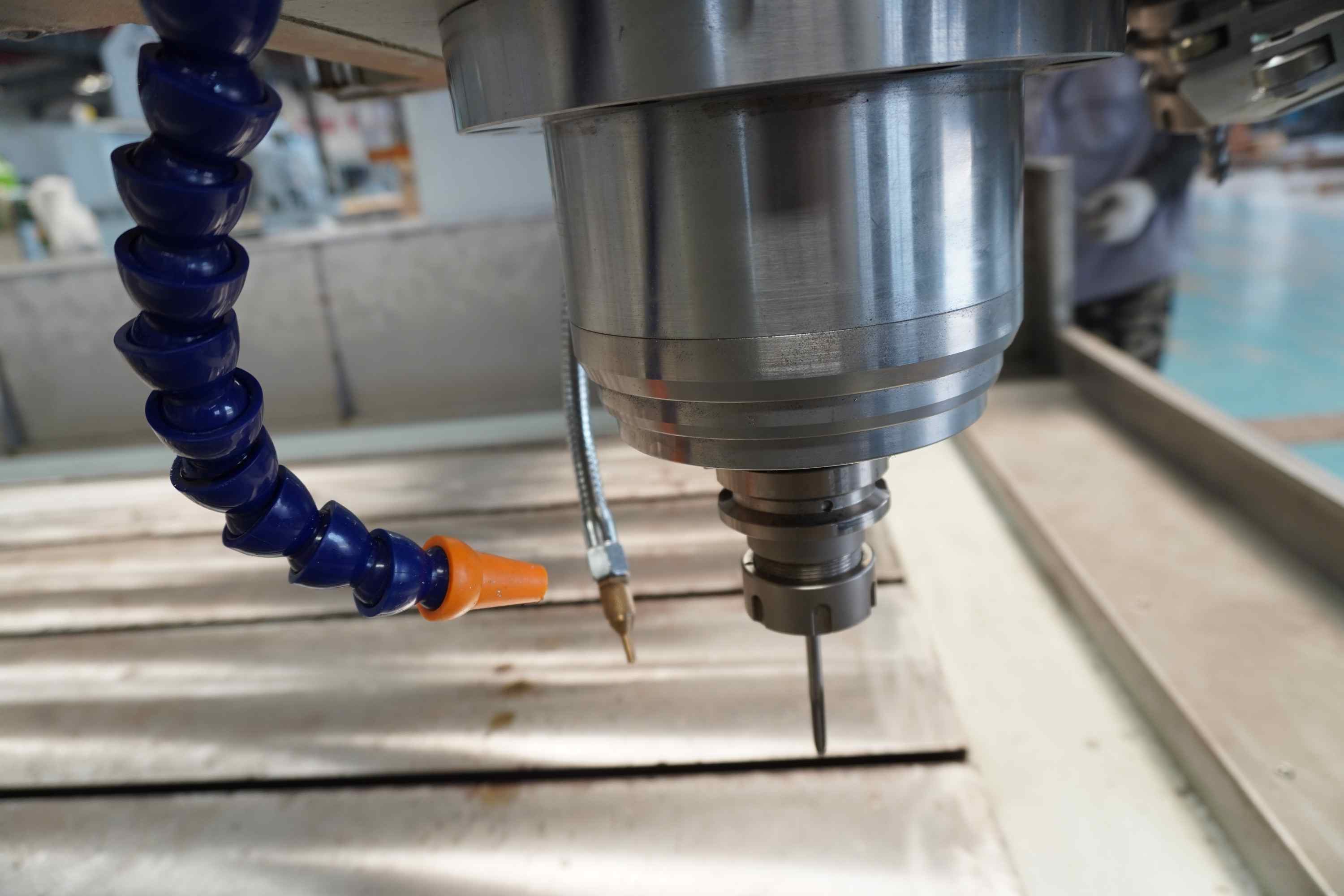
2.Spindle Speed & Torque – Low RPM (8,000–12,000) with high torque prevents bit wear and overheating.

3.Proper Tooling – Use carbide single or two-flute bits designed for aluminum. Avoid HSS tools.

4.Coolant/Lubrication – Mist or air blast systems prevent chip welding and extend tool life.

5.Slow Feed & Plunge Rates – Too fast = broken bits. Start with 30–50 IPM for 1/8″ aluminum sheet.

⚠️ Limitations:

Steel, stainless, or titanium? Not recommended. Heat and vibration will damage a standard router.

Thick metal (>6mm) is challenging; multiple passes needed.

Surface finish won’t match a mill.

For Global Buyers:

If you’re sourcing CNC routers for light metal work, ask suppliers about:

Spindle type (air-cooled vs. water-cooled)

Maximum metal cutting depth per pass

Chip evacuation system

Pro Tip: Machines labeled “aluminum-capable” often include reinforced gantries and shielded electronics. Always request test cuts before bulk ordering.


Bottom Line: A CNC router is a cost-effective entry into metal cutting – for thin sheets and soft alloys. For heavy-duty metalwork, invest in a CNC mill or plasma cutter.


Need sourcing help? Contact us for vetted CNC router suppliers who specialize in light metal fabrication. ✨


📩 Looking for a reliable but affordable CNC solution?
Send us a message for factory-direct pricing.
Read More
WhatsApp:+86 15358102610
📧 Email: zhouni@jsmdzn.com
🌐 Website:https://www.mdzncnc.com/